ASA Interface Addressing, Names and Security Levels
In order for a ASA firewall to function you must first configure interface addressing, interface names and Security Levels which can be considered security zones represented by a number. This lab will discuss and demonstrate the configuration and verification of Interface Addressing, Interface Names and Security Levels.
- Core Knowledge
- Lab Topology
- Initial Configs
- Lab Objectives
- Lab Instruction
Core Knowledge and Real World Scenarios
There are three types of Cisco ASA firewall configurations which you may encounter on your network security journey. The first being Routed followed by multiple context and than there is transparent. This workbook will discuss and demonstrate the configuration of all three types however will primarily focus on routed firewalls. With that being said lets get the basics out of the way.
First lets look at the routed firewall which by the way is the default mode for Cisco ASA’s. Basically a Routed ASA operates as a router with a build in firewall. Routed firewalls have IP Addresses assigned to its interfaces which can be physical or logical based on model. For example the 5510 has Ethernet interfaces and you assign the IP Addresses to these physical interfaces whereas the 5505, 5506-X and 5508-X uses VLAN interfaces and the physical ports are assigned as access VLAN switchports thus the IP addresses are assigned to the VLAN interfaces like a layer 3 switch.
Nearly all firewalls placed into production are routed firewalls and with that in mind when configuring a routed firewall you’ll need to assign IP addressing to the interfaces as well as interface names and security levels.
The most common routed firewall design you’ll encounter will have three security zones; INSIDE, OUTSIDE (or INTERNAL/EXTERNAL) and DMZ. Some firewalls may have DMZ1, DMZ2, and DMZ3 for different compliance regulations such as PCI, HIPAA, SAS70 and others.
Interface names are used during configuration to simplify and identify specific zones. For example, the interface with a name of OUTSIDE will by default get a security level of 0 and is often times used as the interface connected to the internet. The interface name INSIDE, is commonly used for the protected inside network and get the default security level of 100.
When configuring the interface with the name “DMZ” or any other name it will not automatically get a security level assigned to it like the INSIDE and OUTSIDE interfaces do. You must manually assign this security level. Most commonly this level is 50 for a single DMZ interface or 20 40 and 60 for DMZ1, DMZ2 and DMZ3. With this design in mind any traffic sourced from a WEB Server on the DMZ network destined to the DB Server in the INSIDE network must explicitly be permitted by an ACL.
Security levels on the Cisco ASA is a concept that was inherited from the PIX firewalls whereas the rule of thumb goes, a node connected to higher security level can initiate communications with a node reachable via the firewall out a lower security level interface however a node attempting to initiate IP communication from a lower security level to a node in a Higher security level would be denied unless implicitly permitted by an ACL.
In a nut shell a security level is basically a method of assigning a numerical value level of trust to a specific zone or interface.
For Example; You have an ACL on the OUTSIDE interface denying ALL inbound traffic and a PC located on a network connected to the INSIDE interface wants to communicate to an OUTSIDE host. The firewall will inspect this traffic to ensure it meets protocol compliance and pass the traffic if no ACL exist. During this process the firewall places a dynamic entry into the stateful table which allows the return traffic to re-enter the firewall ignoring the ACL as the stateful table is processed first. As the firewall already knows what to expect for the return traffic, it can place the exact ACL entry needed to permit only the return traffic for that specific TCP/UDP session.
IP Addressing on Cisco ASA Interfaces are configure in the same manner as the Cisco IOS Software using the ip address x.x.x.x y.y.y.y whereas x.x.x.x equals the IP Address and y.y.y.y equals the subnet mask.
In order for an interface to become operational an interface name and security-level MUST be assigned. This name can be assigned using the nameif command under interface configuration mode. For example; nameif INSIDE
If you need to manually configure a security level, you would use the security-level {0-100} command under interface configuration mode where 0-100 would be the level of trust. Example; security-level 50
Now lets take what you’ve just learned and expand on that foundation with Multiple Context. Just imagine for a minute that you apply a “virtualization” concept such as VMWare to a Cisco ASA… This is how Multiple Context works. When configuring an ASA 5510 or greater in multiple context mode, you have the ability to “carve” up different context (virtual firewall’s) on the physical ASA which can be used as normal firewalls with the excepted of a few unsupported features which will be discussed in Lab 7-26.
When working with context(s) the same routed firewall rules apply such as Interface Names, Security Levels, routing tables, policies, ACL’s, etc…
Lastly lets take a look at transparent firewalls. This type of firewall configuration is often times known as a “bump in the wire” whereas there is no routed interfaces in which the traffic traversing the firewall is routed to so with that in mind this firewall is not another “hop” in the transit path to a destination but effectively a transparent bump in the wire that can inspect traffic and make traffic decisions based on policies configured such as ACL’s. Transparent firewalls evolved from the IDS/IPS technology from the early 90’s and when configured correctly can be the most effective way of securing two security zones.
One of the biggest problems you may encounter with a transparent firewall is troubleshooting. For example, Host A cannot communicate with Host B and these two hosts are on the same layer 2 network but you may notice that nearly all traffic between the two devices except specific types of traffic is getting dropped. If you did not know there was a transparent firewall between the two devices you’d be pulling your hair out.
Transparent firewalls are an extremely powerful way of securing two separate security zones without letting people know there is a firewall in the transit path. To learn more on Transparent Firewalls check out Lab 7-27
Familiarize yourself with the following command(s);
| Command | Description |
|---|---|
| ip address x.x.x.x y.y.y.y | This command when executed in interface configuration mode statically sets an IP Address. |
| nameif NAME | This command when executed in interface configuration mode sets the name of the interface. |
| security-level 0-100 | This command when executed in interface configuration mode sets the security trust level of the interface. |
Lab Logical Topology
The following logical topology is used in all labs found through out Section 7 of the CCNA Security Workbook;
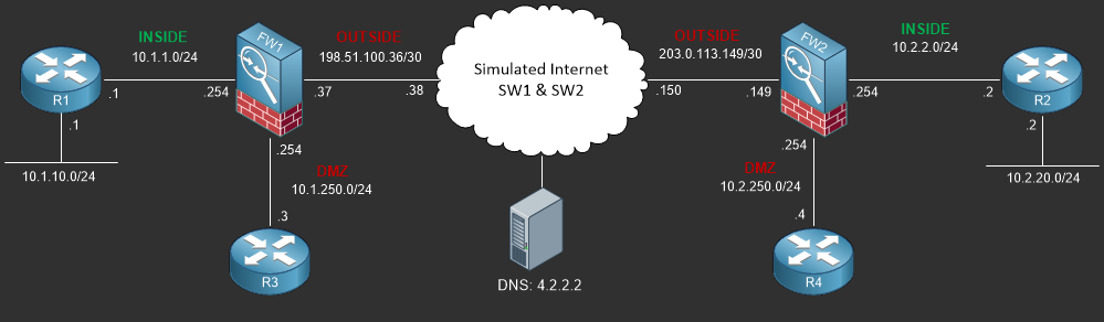
To view the physical cabling topology please visit the Topology page.
Lab Device Initial Configurations
In Section 7 you’ll only be configuring FW1. You will however use other lab devices to verify your configuration on FW1.
If you completed the previous lab you can continue where you left off otherwise you’ll need to load the following initial configurations into their respective device(s);
Section 7 Pre-Configured Lab Device(s)
The following lab devices have been pre-configured to save you time as you’ll only be working with FW1 in Section 7.
In order to complete the labs in section 7 you MUST load the following pre-configuration(s);
Before you Start
This lab requires that you have access to a Cisco ASA. You can complete this lab using a virtual Cisco ASA within GNS3 or you can reserve free lab time on the Stub Lab to have access to a pair of Cisco ASA 5510 Series Firewalls which can be used to complete this lab.
Lab Objectives
In this lab you will complete the following objectives.
- On FW1 configure Ethernet0/0 as the OUTSIDE interface with the IP Address of 198.51.100.37/30 and verify your interface configuration.
- On FW1 configure Ethernet0/1 as INSIDE interface with the IP Address of 10.1.1.254/24 and verify your interface configuration.
- On FW1 configure Ethernet0/2 as the DMZ interface with a Security Level of 50 and the IP Address of 10.1.250.254/24 then verify your interface configuration.
One More Thing…
It is recommended that you attempt to complete these lab objectives the first time without looking at the Lab Instruction section.
If you are a student preparing for the Cisco CCNA Security Certification Exam than you are more likely to remember how to complete these objectives if you
attempt to complete them the first time on your own with the use of the core knowledge section found in this lab. You should only resort to the Lab Instruction
section to verify your work.
Lab Instruction
Objective 1. – On FW1 configure Ethernet0/0 as the OUTSIDE interface with the IP Address of 198.51.100.37/30 and verify your interface configuration.
FW1# config terminal
FW1(config)# interface ethernet0/0
FW1(config-if)# ip address 198.51.100.37 255.255.255.252
FW1(config-if)# nameif OUTSIDE
INFO: Security level for "OUTSIDE" set to 0 by default.
FW1(config-if)# no shutdown
FW1(config-if)# show run interface ethernet0/0
!
interface Ethernet0/0
 nameif OUTSIDE
 security-level 0
 ip address 198.51.100.37 255.255.255.252
FW1(config-if)#
Objective 2. – On FW1 configure Ethernet0/1 as INSIDE interface with the IP Address of 10.1.1.1/24 and verify your interface configuration.
FW1(config-if)# interface ethernet0/1
FW1(config-if)# ip address 10.1.1.254 255.255.255.0
FW1(config-if)# nameif INSIDE
INFO: Security level for "INSIDE" set to 100 by default.
FW1(config-if)# no shutdown
FW1(config-if)# show run interface ethernet0/1
!
interface Ethernet0/1
 nameif INSIDE
 security-level 100
 ip address 10.1.1.254 255.255.255.0
FW1(config-if)#
Objective 3. – On FW1 configure Ethernet0/2 as the DMZ interface with a Security Level of 50 and the IP Address of 10.10.1.1/24 then verify your interface configuration.
FW1(config-if)# interface ethernet0/2
FW1(config-if)# ip address 10.1.250.254 255.255.255.0
FW1(config-if)# nameif DMZ
FW1(config-if)# security-level 50
FW1(config-if)# no shutdown
FW1(config-if)# show run interface ethernet0/2
!
interface Ethernet0/2
 nameif DMZ
 security-level 50
 ip address 10.1.250.254 255.255.255.0
FW1(config-if)# end
FW1#
The command(s) demonstrated below show additional verification which allows you to view the IP Addressing and interface operational status along with their names and security levels. Interfaces will not show up in the routing table if the interfaces are administratively down. In order for a connected route to be active, the interface has to have an interface name and IP Address.
FW1# show interface ip brief
Interface                  IP-Address      OK? Method Status                Protocol
Ethernet0/0                198.51.100.37   YES manual up                    up
Ethernet0/1                10.1.1.254      YES manual up                    up
Ethernet0/2                10.1.250.254    YES manual up                    up
Ethernet0/3                unassigned      YES unset  administratively down down
Management0/0              unassigned      YES unset  administratively down down
FW1# show nameif
Interface                Name                     Security
Ethernet0/0              OUTSIDE                    0
Ethernet0/1              INSIDE                   100
Ethernet0/2              DMZ                       50
FW1# show route

Codes: C - connected, S - static, I - IGRP, R - RIP, M - mobile, B - BGP
       D - EIGRP, EX - EIGRP external, O - OSPF, IA - OSPF inter area
       N1 - OSPF NSSA external type 1, N2 - OSPF NSSA external type 2
       E1 - OSPF external type 1, E2 - OSPF external type 2, E - EGP
       i - IS-IS, L1 - IS-IS level-1, L2 - IS-IS level-2, ia - IS-IS inter area
       * - candidate default, U - per-user static route, o - ODR
       P - periodic downloaded static route

Gateway of last resort is not set

C    198.51.100.36 255.255.255.252 is directly connected, OUTSIDE
C    10.1.250.0 255.255.255.0 is directly connected, DMZ
C    10.1.0.0 255.255.255.0 is directly connected, INSIDE
FW1#
