RIP Default Information Originate
Configuring static default routes on every single network device in the infrastructure is cumbersome. This function can be done automagically with default route propogation in RIP known as default information originate. This lab will discuss and demonstrate the configuration and verification of RIP Default Information Originate.
Real World Application & Core Knowledge
So lets say you have a boundary router that has a direct connection to the internet and you want RIP to advertise the internet as a route known as a “default route”. As previously discussed in Lab 6-3. Ideally a network engineer would not want to go to every single node in the network to configure a static default route so generally they would use a dynamic routing protocol to advertise the network 0.0.0.0/0.
RIP has a built in feature in which allows it to advertise a default route to its direct neighbors which will propagate throughout the entire RIP routing domain. Utilizing this type of configuration can a company money due to the man hours required to configure a static default route on each and every router and/or switch in the network and that does not include general router/switch maintenance.
Advertising a default route via RIP is done by a single command that is executed in RIP router configuration mode. This command is default-information originate
This lab will continue to build upon the same logical topology used previously in Lab 7-6 as shown below;
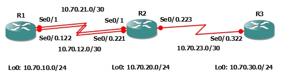
In this lab you will configure R3 to advertise a default route throughout the RIP routing domain.
Familiarize yourself with the following new command(s);
| Command | Description |
|---|---|
| default-information originate | This command is executed in RIP router configuration mode to configure RIP to advertise a default route throughout the RIP routing domain. |
Lab Prerequisites
- If you are using GNS3 than load the Free CCNA Workbook GNS3 topology than start devices; R1, R2 and R3.
- Establish a console session with devices R1, R2 and R3 than load the initial configurations provided below by copying the config from the textbox and pasting it into the respected routers console.
Lab Objectives
- Configure R3 to advertise a default route via the Routing Information Protocol (RIP).
- Verify that the default route is properly propagated from R3 to R2 and R1 by viewing the RIP database and routing table on R1 and R2.
Lab Instruction
Objective 1. – Configure R3 to advertise a default route via the Routing Information Protocol (RIP).
R3>enable
R3#configure terminal
Enter configuration commands, one per line.  End with CNTL/Z.
R3(config)#router rip
R3(config-router)#default-information originate
R3(config-router)#end
R3#
Objective 2. – Verify that the default route is properly propagated from R3 to R2 and R1 by viewing the RIP database and routing table on R1 and R2.
R2#show ip rip database
0.0.0.0/0    auto-summary
0.0.0.0/0
    [1] via 10.70.23.2, 00:01:56 (permanent), Serial0/0.223
   * Triggered Routes:
     - [1] via 10.70.23.2, Serial0/0.223
10.0.0.0/8    auto-summary
10.30.0.0/22
    [1] via 10.70.23.2, 00:08:47 (permanent), Serial0/0.223
   * Triggered Routes:
     - [1] via 10.70.23.2, Serial0/0.223
10.70.10.0/24
    [1] via 10.70.12.1, 00:00:16, Serial0/0.221
10.70.12.0/30    directly connected, Serial0/0.221
10.70.20.0/24    directly connected, Loopback0
10.70.21.0/30    directly connected, Serial0/1
10.70.21.1/32    directly connected, Serial0/1
10.70.23.0/30    directly connected, Serial0/0.223
10.70.30.0/24
    [1] via 10.70.23.2, 00:08:47 (permanent), Serial0/0.223
   * Triggered Routes:
     - [1] via 10.70.23.2, Serial0/0.223
R2#show ip route
Codes: C - connected, S - static, R - RIP, M - mobile, B - BGP
       D - EIGRP, EX - EIGRP external, O - OSPF, IA - OSPF inter area
       N1 - OSPF NSSA external type 1, N2 - OSPF NSSA external type 2
       E1 - OSPF external type 1, E2 - OSPF external type 2
       i - IS-IS, su - IS-IS summary, L1 - IS-IS level-1, L2 - IS-IS level-2
       ia - IS-IS inter area, * - candidate default, U - per-user static route
       o - ODR, P - periodic downloaded static route

Gateway of last resort is 10.70.23.2 to network 0.0.0.0

     10.0.0.0/8 is variably subnetted, 8 subnets, 4 masks
R       10.30.0.0/22 [120/1] via 10.70.23.2, 00:09:16, Serial0/0.223
C       10.70.12.0/30 is directly connected, Serial0/0.221
R       10.70.10.0/24 [120/1] via 10.70.12.1, 00:00:19, Serial0/0.221
R       10.70.30.0/24 [120/1] via 10.70.23.2, 00:09:16, Serial0/0.223
C       10.70.21.1/32 is directly connected, Serial0/1
C       10.70.20.0/24 is directly connected, Loopback0
C       10.70.21.0/30 is directly connected, Serial0/1
C       10.70.23.0/30 is directly connected, Serial0/0.223
R*   0.0.0.0/0 [120/1] via 10.70.23.2, 00:02:26, Serial0/0.223
R2#
As you can see from R2’s RIP database that the route 0.0.0.0/0 is being learned via 10.70.23.2 on Serial0/0.223. According to the routing table, the router will route 0.0.0.0/0 to 10.70.23.2 as the default route is learned via RIP as denoted by the R*
R1#show ip rip database
0.0.0.0/0    auto-summary
0.0.0.0/0
    [2] via 10.70.21.2, 00:00:00, Serial0/1
    [2] via 10.70.12.2, 00:00:15, Serial0/0.122
10.0.0.0/8    auto-summary
10.30.0.0/22
    [2] via 10.70.21.2, 00:00:00, Serial0/1
    [2] via 10.70.12.2, 00:00:15, Serial0/0.122
10.70.10.0/24    directly connected, Loopback0
10.70.12.0/30    directly connected, Serial0/0.122
10.70.20.0/24
    [1] via 10.70.21.2, 00:00:00, Serial0/1
    [1] via 10.70.12.2, 00:00:15, Serial0/0.122
10.70.21.0/30    directly connected, Serial0/1
10.70.21.2/32    directly connected, Serial0/1
10.70.23.0/30
    [1] via 10.70.21.2, 00:00:00, Serial0/1
    [1] via 10.70.12.2, 00:00:15, Serial0/0.122
10.70.30.0/24
    [2] via 10.70.21.2, 00:00:00, Serial0/1
    [2] via 10.70.12.2, 00:00:15, Serial0/0.122
R1#show ip route
Codes: C - connected, S - static, R - RIP, M - mobile, B - BGP
       D - EIGRP, EX - EIGRP external, O - OSPF, IA - OSPF inter area
       N1 - OSPF NSSA external type 1, N2 - OSPF NSSA external type 2
       E1 - OSPF external type 1, E2 - OSPF external type 2
       i - IS-IS, su - IS-IS summary, L1 - IS-IS level-1, L2 - IS-IS level-2
       ia - IS-IS inter area, * - candidate default, U - per-user static route
       o - ODR, P - periodic downloaded static route

Gateway of last resort is 10.70.21.2 to network 0.0.0.0

     10.0.0.0/8 is variably subnetted, 8 subnets, 4 masks
R       10.30.0.0/22 [120/2] via 10.70.21.2, 00:00:02, Serial0/1
                     [120/2] via 10.70.12.2, 00:00:17, Serial0/0.122
C       10.70.12.0/30 is directly connected, Serial0/0.122
C       10.70.10.0/24 is directly connected, Loopback0
R       10.70.30.0/24 [120/2] via 10.70.21.2, 00:00:02, Serial0/1
                      [120/2] via 10.70.12.2, 00:00:17, Serial0/0.122
R       10.70.20.0/24 [120/1] via 10.70.21.2, 00:00:04, Serial0/1
                      [120/1] via 10.70.12.2, 00:00:18, Serial0/0.122
C       10.70.21.0/30 is directly connected, Serial0/1
R       10.70.23.0/30 [120/1] via 10.70.21.2, 00:00:04, Serial0/1
                      [120/1] via 10.70.12.2, 00:00:18, Serial0/0.122
C       10.70.21.2/32 is directly connected, Serial0/1
R*   0.0.0.0/0 [120/2] via 10.70.21.2, 00:00:05, Serial0/1
               [120/2] via 10.70.12.2, 00:00:20, Serial0/0.122
R1#
As shown above, R1’s route to 0.0.0.0/0 is being learned via 10.70.12.1 and 10.70.21.2 as there are redundant links between R1 and R2.
To further verify that the default route is operating as planned you can do a traceroute on R1 to any ip address not in in the routing table such as 4.2.2.2 and it should load balanced towards R2 and then hit R3 before it returns and ICMP host unreachable as shown below;
R1#traceroute 4.2.2.2

Type escape sequence to abort.
Tracing the route to 4.2.2.2

  1 10.70.21.2 13 msec
    10.70.12.2 16 msec
    10.70.21.2 12 msec
  2 10.70.23.2 28 msec 24 msec 32 msec
  3 10.70.23.2 !H  !H  *
R1#
When doing a traceroute on a Cisco device, you may encounter several different types of responses represented by different letters. These letters have been listed out below to better your understanding of the traceroute and ping command(s);
| Response | Description |
|---|---|
| ! | Successful and/or response received. |
| * | Timed out |
| N | Network Unreachable, commonly caused by incomplete routing information. |
| H | Host Unreachable, commonly caused by an ACL. |
| P | Protocol Unreachable |
| A | Administratively Denied |
| Q | Source Quench received |
| ? | Unknown (any other ICMP message) |
