So with the NSA, the CIA and the FBI sucking up every bit they possibly can on the internet at countless locations around the world you wonder how could you possibly become anonymous on the interwebz? Of course it’s not just the United States Government that feels the need that you as an individual should sacrifice your liberty for security, this practice is becoming quite common all around the globe from the United Kingdom all the way down under in the land of the happy kangaroos (Australia of course). Just for the record I’m sure the kangaroo’s don’t give a shit because they don’t feel their privacy is violated.
As the world awakens to the vast over reach of Government around the globe people are looking for new and innovative ways to retain and/or regain their privacy. As a network engineer I wanted to share one of many methods I use to remain anonymous on the internet.
So first lets ask a big question. Why would you want to remain anonymous on the internet? Think about that for a minute.
As a network engineer or an individual aspiring to become a network engineer you will quickly realize or learn that you can easily be singled out on the internet with just an IP address. Your IP Address can be used to locate you geographically speaking.
For example lets say your computer is infected with a virus and you become an unwilling participate in a hack that is orchestrated by individuals attempting to gain access into classified computer networks to gather information. You personally would be held responsible, after all it is your IP Address that is doing the hacking. Your IP address along with the date and time included in subpoena sent to your ISP could easily identify you and the home address related to the service. Next thing you know you have the SWAT team busting your door down while you’re watching reality TV of SWAT teams busting peoples door down. How is that for irony?
So how do you solve this problem? Through the use of VPN technology. There are several VPN providers on the internet who’s sole purpose is to provide anonymity online. You pay for the service and they provide you with the credentials to connect to a VPN. After you’ve connected all your internet traffic traverses their network and any internet request that are made are made through the VPN. So now your public IP Address is not the IP Address provided to you by your ISP which can be used to identify you but rather the public IP address used by the anonymous VPN service.
While using Anonymous VPN services can be used to commit illegal crimes such as downloading and distributing copyrighted material or perhaps even other nefarious actions, Free CCNA Workbook does not promote or endorse any of these actions. With that being said anything you do on anonymous vpn services is at your own risk.
Beyond the Basics
Traditionally anonymous VPN services are typically used via Dialer interfaces on common operating systems such as Windows and Linux. While this configuration works, it only works for a single PC unless you want to configure a Windows Server with connection sharing which of course is a huge pain in the @$$.
Using a Cisco IOS router you can than allow multiple PC’s to use the VPN service by changing the default gateway on the PC(s) to the inside interface of the VPN Client. You can even go a step further by setting up a separate SSID on your wireless access point(s) so that you have a dedicated wireless SSID which only uses the anonymous VPN service as its connection to the internet.
There are tons of Anonymous VPN Providers out there however this blog is going to demonstrate the configuration of an L2TP IPSEC using Private Internet Access
So enough with all the jibble jabble lets dive in to the config shall we?
The L2TP IPSEC Tunnel Configuration
Well I’m not going to explain every single line of configuration however if you are experienced enough in Cisco IOS and VPN technologies this should all make sense. If you have questions you can post a comment with your question.
Before you get started you’re going to need the credentials for your VPN Authentication. The credentials you got in your email when you signed up with Private Internet Access is NOT the credentials you’ll be using to connect to the VPN. You must log into the Client Support Page and generate new vpn credentials which will be used. Once you have the credentials you’ll need the peer IP address which you’ll be connecting to.
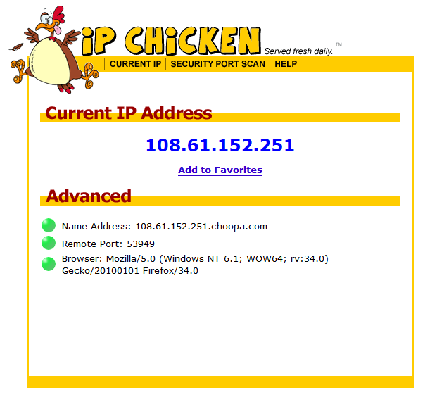
You can obtain this by pinging the DNS name of the VPN gateway you wish to connect to. In this case we’re going to use East US Gateway “us-east.privateinternetaccess.com” At the time of this blog this name resolves to 108.61.152.251. This of course will probably change by the time you read this.
Once you have all this information you’re ready to start configuration. Go ahead and configure hostname, ssh, credentials, IP addresses, etc…
You’re also going to need a PUBLIC IP address for this configuration, for this blog we’re using 73.41.232.21 on FastEthernet0/0
First up we need to configure Phase 1 of the IPSEC Tunnel by defining the ISKMP policies and peer pre-shared key.
!
crypto isakmp policy 10
 encr aes 256
 authentication pre-share
 group 5
!
crypto isakmp key mysafety address 108.61.152.251
!
Now lets define the first sequence in the crypto map which will be used to build the security association;
!
crypto map PIA_VPN 10 ipsec-isakmp
 set peer 108.61.152.251
 set transform-set ESP-AES256-SHA1
 match address PIA_EAST_US
!
You’re going to need to build out the transform set referenced in the crypto map “ESP-AES256-SHA1”;
!
crypto ipsec transform-set ESP-AES256-SHA1 esp-aes 256 esp-sha-hmac
 mode transport
!
Now you need to configure the ACL referenced in the crypto map “PIA_EAST_US”. In this case the source and destination UDP port is going to be 1701. You’ll also need to use the public IP address which should be static as the source IP Address int he ACL. In this case 73.41.232.21 is the IP address assigned to the outside interface FastEthernet0/0 whereas 108.61.152.251 is the VPN Gateway IP Address.
!
ip access-list extended PIA_EAST_US
 permit udp host 73.41.232.21 eq 1701 host 108.61.152.251 eq 1701
!
Once the IPSEC Configuration has been completed you’ll need to assign the crypto map to the public facing IP Address, in this case FastEthernet0/0;
!
interface FastEthernet0/0
 crypto map PIA_VPN
!
Before we can configure the L2TP virtual tunnel interface we first need to define the pseudowire class configuration. The encapsulation will be set to l2tpv2 and the local interface should be defined as the public facing interface;
!
pseudowire-class PIA_L2TP
 encapsulation l2tpv2
 ip local interface FastEthernet0/0
!
Now we can define the virtual tunnel interface, in this case its going to be a Virtual-PPP Interface;
interface Virtual-PPP1
 description Tunnel to PIA EAST US
 ip address negotiated
 ip nat outside
 ip virtual-reassembly
 ppp eap refuse
 ppp chap hostname x4108222
 ppp chap password 0 8Mz1wHgZDJ
 ppp ipcp address accept
 no cdp enable
 pseudowire 108.61.152.251 1 pw-class PIA_L2TP
And thats it for the L2TP IPSEC Tunnel configuration. You should now be able to verify that Phase I and Phase II have established successfully as shown below;
PIA-GATEWAY#show crypto isakmp sa
IPv4 Crypto ISAKMP SA
dst             src             state          conn-id status
108.61.152.251  73.41.232.21    QM_IDLE           1001 ACTIVE

IPv6 Crypto ISAKMP SA

PIA-GATEWAY#
PIA-GATEWAY#show crypto ipsec sa

interface: FastEthernet0/0
    Crypto map tag: PIA_VPN, local addr 73.41.232.21

   protected vrf: (none)
   local  ident (addr/mask/prot/port): (73.41.232.21/255.255.255.255/17/1701)
   remote ident (addr/mask/prot/port): (108.61.152.251/255.255.255.255/17/1701)
   current_peer 108.61.152.251 port 500
     PERMIT, flags={origin_is_acl,}
    #pkts encaps: 305, #pkts encrypt: 305, #pkts digest: 305
    #pkts decaps: 294, #pkts decrypt: 294, #pkts verify: 294
    #pkts compressed: 0, #pkts decompressed: 0
    #pkts not compressed: 0, #pkts compr. failed: 0
    #pkts not decompressed: 0, #pkts decompress failed: 0
    #send errors 1, #recv errors 0

     local crypto endpt.: 73.41.232.21, remote crypto endpt.: 108.61.152.251
     path mtu 1500, ip mtu 1500, ip mtu idb FastEthernet0/0
     current outbound spi: 0xC4E6F422(3303470114)
     PFS (Y/N): N, DH group: none

     inbound esp sas:
      spi: 0x97AF5057(2544848983)
        transform: esp-256-aes esp-sha-hmac ,
        in use settings ={Transport, }
        conn id: 2001, flow_id: NETGX:1, sibling_flags 80000006, crypto map: PIA_VPN
        sa timing: remaining key lifetime (k/sec): (4580055/1730)
        IV size: 16 bytes
        replay detection support: Y
        Status: ACTIVE

     inbound ah sas:

     inbound pcp sas:

     outbound esp sas:
      spi: 0xC4E6F422(3303470114)
        transform: esp-256-aes esp-sha-hmac ,
        in use settings ={Transport, }
        conn id: 2002, flow_id: NETGX:2, sibling_flags 80000006, crypto map: PIA_VPN
        sa timing: remaining key lifetime (k/sec): (4580054/1730)
        IV size: 16 bytes
        replay detection support: Y
        Status: ACTIVE

     outbound ah sas:

     outbound pcp sas:
PIA-GATEWAY#
If you are having problems with Phase I or Phase II you can use the debug crypto isakmp and debug crypto ipsec command(s) to help you better understand why. Google any errors you may receive 🙂
If your configuration is correct thus far the Virtual-PPP1 interface should be up/up with an IP Address as shown below;
PIA-GATEWAY#show interface virtual-ppp1
Virtual-PPP1 is up, line protocol is up
  Hardware is Virtual PPP interface
  Description: Tunnel to PIA EAST US
  Internet address is 10.10.1.3/32
  MTU 1500 bytes, BW 100000 Kbit/sec, DLY 100000 usec,
     reliability 255/255, txload 1/255, rxload 1/255
  Encapsulation PPP, LCP Open
  Open: IPCP, loopback not set
  Keepalive set (10 sec)
  DTR is pulsed for 1 seconds on reset
  Last input 00:05:43, output never, output hang never
  Last clearing of "show interface" counters 00:50:30
  Input queue: 0/75/0/0 (size/max/drops/flushes); Total output drops: 0
  Queueing strategy: fifo
  Output queue: 0/40 (size/max)
  5 minute input rate 0 bits/sec, 0 packets/sec
  5 minute output rate 0 bits/sec, 0 packets/sec
     417 packets input, 5892 bytes, 0 no buffer
     Received 0 broadcasts, 0 runts, 0 giants, 0 throttles
     0 input errors, 0 CRC, 0 frame, 0 overrun, 0 ignored, 0 abort
     339 packets output, 6217 bytes, 0 underruns
     0 output errors, 0 collisions, 0 interface resets
     0 unknown protocol drops
     0 output buffer failures, 0 output buffers swapped out
     0 carrier transitions
PIA-GATEWAY#
If your Virtual-PPP1 interface is failing to obtain an IP Address and shows UP/DOWN than you can use the debug ppp authentication command to ensure that your credentials are correct.
Routing and NAT Configuration
Before the clients on the inside can access the internet via the L2TP IPSEC VPN you need to setup two static routes and NAT.
The first static route you’ll need is a route to the VPN Gateway via your ISP default gateway. In this case 108.61.152.251 needs to be routed to 73.41.232.1
!
ip route 108.61.152.251 255.255.255.255 73.41.232.1
!
Next is going to be the default route for all traffic to reach the internet, send it through the tunnel;
!
ip route 0.0.0.0 0.0.0.0 Virtual-PPP1
!
Next up you need to define the inside and outside NAT zones;
!
interface FastEthernet0/1
 ip nat inside
!
interface Virtual-PPP1
 ip nat outside
!
Once NAT zones have been defined you’ll need to define an ACL which will be used by NAT overload to translate multiple inside machines to the IP address of the virtual-ppp interface. In this case our inside network is 192.168.0.0/24
!
ip access-list standard NAT
 permit 192.168.0.0 0.0.255.255
!
Finally we need to define the source NAT statement so that inside hosts referenced by the named acl “NAT” will be overloaded to the Virtual-PPP1 interface.
!
ip nat inside source list NAT interface Virtual-PPP1 overload
!
Now you’re golden. To test your NAT configuration you can do a traceroute sourced from your inside interface, in this case FastEthernet0/1 to 4.2.2.2 as demonstrated below;
PIA-GATEWAY#traceroute 4.2.2.2 source FastEthernet0/1 probe 1 numeric

Type escape sequence to abort.
Tracing the route to 4.2.2.2

  1 10.10.1.1 48 msec
  2  *
  3 184.75.211.129 64 msec
  4 38.88.240.133 88 msec
  5 69.31.143.24 60 msec
  6 154.54.3.93 76 msec
  7 4.69.155.208 128 msec
  8 4.2.2.2 112 msec
PIA-GATEWAY#
As you can see from the traceroute provided above the next hop IP address is going to be 10.10.1.1 which is the IP address of the VPN gateway.
To allow machines on your network to access the internet via this newly build L2TP IPSEC VPN Gateway you just need to change the default gateway on your machines to the inside interface of the newly configured vpn gateway router.
After which you can test your public facing IP address using IP Chicken!
Download the final Configuration!
Click the button below to download the final configuration!
If you have any questions or comments please post a comment below! Enjoy….

Recent Comments