Configuring Native VLAN on a Trunk Links
The 802.1q native Vlan is commonly misunderstood and often times very confusing for individuals learning the technology. This lab will discuss what the native vlan is and how it works and also how to implement a native vlan on a catalyst trunk link.
- Core Knowledge
- Lab Topology
- Initial Configs
- Lab Objectives
- Lab Instruction
Core Knowledge and Real World Scenarios
In order to understand how the 802.1q native vlan works you must first understand 802.1q encapsulation. First off lets start with a picture of a frame as shown below;
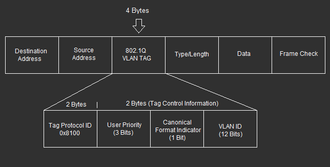
Inside a Layer 2 frame there is a four byte tag used for 802.1q, this tag is divided into 4 fields. The Tag Protocol ID (ethertype) which for 802.1q trunking will always be 0x8100, the user priority which is 3 bits and this is used for Class of Service (802.1p) which is a QoS mechanism on trunk interfaces between switches, the CFI (Canonical Format Indicator) which is now used as the DEI (Drop Eligible Indicator) which specifies if there is traffic congestion this frame may be dropped if set to 1 and finally the VLAN ID which is a 12 bit number 0-4095.
When most people think of 802.1q they commonly think of the VLAN ID which is the 12 bit number in the dot1q tag. This tag identifies which vlan the specific frame belongs to. If this 12 bit field was “100001010100” then it would belong to VLAN_2132.
You derive this number from adding up the binary bits; (2048,1024,512,256,128,64,32,16,8,4,2,1) in their respective order. So in this example, 2048+64+14+4=2132
Now that you have an understanding of the VLAN ID field in the dot1q tag the question can finally be asked, what is the native vlan?
Well in a nut shell, the native vlan is a configuration on a switch port or layer 2 interface in which untagged frames are placed into a given VLAN. By default on a Cisco Catalyst switch, the native vlan is 1.
Lets say you have two switches connected together via 802.1q trunk. When these switches exchange layer 2 frames over this trunk link that do NOT have a dot1q tag, the switches know automatically that this traffic belongs into the native vlan, which by default is 1.
The native vlan CAN be changed on a per trunk basis. Lets say you want the native vlan to be 10 then the you would use the command switchport trunk native vlan 10 on the switchport interface and this will make the switch place any untagged frames sent or received into VLAN 10. You can however bridge VLAN’s using two separate native VLAN’s on each side of the trunk link however this may cause undesirable affects such as layer 2 loops or security vulnerabilities. Bridging VLAN’s using native vlan configuration via trunk links is not commonly used nor recommended.
Other things to consider when dealing with the native vlan on a trunk link is that catalyst switches will place general control plane traffic into the native vlan unless configured otherwise. This traffic includes PVST BPDU’s, DTP, CDP, LLDP. This layer 2 traffic is sent via the native vlan which by default is VLAN_1 however if the native vlan is changed on a per trunk interface basis then the traffic is sent untagged and placed into the administratively configured native vlan.
The native vlan is commonly used on layer 3 devices that cannot understand dot1q tags however this is slowly becoming a thing of the past.
One of the most common configurations you’ll see where the native vlan is used is when configuring an edge access port as a trunk interface allowing only two VLAN’s, the Native VLAN which is what the PC is used on because by default workstations only send/receive on the native VLAN’s and the VOICE VLAN used for VoIP Telephones.
So with that in mind, we have vlan 10 and vlan 20. VLAN 10 is the native data vlan which PC’s will use and VLAN 20 is used for VOICE. You plug in the VoIP Telephone and the phone boots up and pulls a DHCP IP address which contains a DHCP Option which includes the Voice vlan information. The phone uses this information to configure the phone, which releases and renews the DHCP IP address of the telephone in VLAN 20. Since the telephone has a built in switch and supports 802.1q, the phone forwards all VoIP traffic using VLAN 20 and passes the native VLAN traffic to the desktop.
The desktop, which is plugged into the PC port of the telephone boots up and pulls an IP address on the native vlan which is 10 as configured on the switch and goes about its happy day being a slave to the user.
Enough with the talking, lets get to walking shall we?
Familiarize yourself with the list of command(s) compiled below;
| Command | Description |
|---|---|
| switchport trunk encapsulation dot1q | This command when executed in interface configuration mode sets trunking encapsulation to the IEEE 802.1q standard. |
| switchport mode trunk | This command when executed in interface configuration mode sets a switchport to trunk, note that encapsulation MUST be set first on most Catalyst switches. |
| switchport trunk native vlan {1-4094} | This command when executed in interface configuration mode that is configured to trunk will set the native vlan which specifies which VLAN untagged traffic belongs to. |
| show interfaces {interface-name} trunk | This command when executed in user and/or privileged mode will display interface trunk information including trunk mode, encapsulation, native vlan, trunk allowed list and pruning. |
Lab Logical Topology
The following logical topology is used in all labs found through out Section 1 of the CCNA Security Workbook;
To view the physical cabling topology please visit the Topology page.
Lab Device Initial Configurations
The following initial configurations are provided as a base configuration to start the lab with. You may copy and paste these configurations directly into the terminal window of Stub Lab devices.
Before you Start
This lab requires real Cisco Switches. You can reserve lab time on the Stub Lab to have free access to Cisco Catalyst 3560 Series switches which can be used to complete this lab. To make things easier you may load the initial configurations provided in this lab as a base config.
Please note that this lab cannot be performed in GNS3 using the NM-16ESW.
Lab Objectives
In this lab you will complete the following objectives.
- On SW1, Create VLAN 10 and name it DATA
- Configure Fa0/1 on SW1 as a trunk interface and set the native VLAN to 10
- Verify the native VLAN on interface FastEthernet0/1 on SW1
Hold on just 1 sec!
It is recommended that you attempt to complete these lab objectives the first time without looking at the Lab Instruction section.
If you are a student preparing for the Cisco CCNA Security Certification Exam than you are more likely to remember how to complete these objectives if you attempt to complete them the first time on your own with the use of the core knowledge section found in this lab. You should only resort to the Lab Instruction section to verify your work.
Lab Instruction
Objective 1. – On SW1, Create VLAN 10 and name it DATA.
SW1>enable
SW1#config t
Enter configuration commands, one per line.  End with CNTL/Z.
SW1(config)#vlan 10
SW1(config-vlan)#name DATA
SW1(config-vlan)#exit
SW1(config)#
Objective 2. – Configure Fa0/1 on SW1 as a trunk interface and set the native VLAN to 10
SW1(config)#interface FastEthernet0/1
SW1(config-if)#switchport trunk encapsulation dot1q
SW1(config-if)#switchport mode trunk
SW1(config-if)#switchport trunk native vlan 10
SW1(config-if)#end
SW1(config)#
Objective 3. – Verify the native VLAN on interface FastEthernet0/1 on SW1.
SW1#show interfaces Fa0/1 trunk

Port        Mode             Encapsulation  Status        Native vlan
Fa0/1       on               802.1q         other         10

Port        Vlans allowed on trunk
Fa0/1       none

Port        Vlans allowed and active in management domain
Fa0/1       none

Port        Vlans in spanning tree forwarding state and not pruned
Fa0/1       none
SW1#
SW1(config)#
